LAB-3
2D FIR DESIGN
INTRODUCTION
In this
exercise, we will focus on the design of 2D finite impulse response (FIR)
filters. In J-DSP, a 2D finite impulse response can be specified in three ways:
First, by the 2D FIR Design1 block that uses a window-based
design (Fig. 1(a)), second, by the 2D FIR Design2 block
that uses the frequency sampling method (Fig. 1(b)), and third, by the 2D FIR
Coeff block in which you type in
the 2D FIR coefficients directly (Fig. 1(c)).

Fig. 1(a) 2D FIR Design1 block Fig. 1(b) 2D FIR Design2 block.

Fig. 1(c) 2D FIR Coeff block
Fig. 2 shows the 2D J-DSP editor. In
fig. 2, the 2D blocks that are placed in the vertical line on the left hand
side are called permanent blocks and are shown in green color. The blocks
placed in the horizontal line are shown in yellow color and can be changed by
selecting one of the options given in the drop-down menu on the top left corner
of the screen. It is always recommended to use any 2D block separately before
it is connected with others and to read the [Help] screen of every new block
you use.
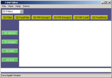
Fig.2 2D
J-DSP
In this lab, we will first study the
design of 2D FIR filters using the window method. We will consider different
windows characteristics and issues associated with separable and non-separable
design techniques. Then we will use frequency-sampling method to design 2D FIR
filters and will compare the quality measures and complexity issues related
with these two design techniques. In FIR filter design, the measure of filter
quality is around 3 numbers: maximum error in the pass-band![]() , maximum error in the stop-band
, maximum error in the stop-band![]() and transition band
and transition band ![]() . As these parameters become smaller, the quality of the
filter improves. The filter order is given by the length of the filter impulse
response and is the measure of complexity.
. As these parameters become smaller, the quality of the
filter improves. The filter order is given by the length of the filter impulse
response and is the measure of complexity.
Note: Give
reasons for all the answers to the questions, and where necessary, give
appropriate J-DSP plots (Time/Frequency-domain) in order to justify your
answers. You may need to use other 2D blocks as well.
Remember, the perspective plot
provides a quick feel for the quality of the filter and the contour plot is
more helpful for measuring the circularity of the pass-band and stop-band.
Design of
2D FIR filters using windows is a spatial domain method; that is, we try to
approximate an ideal impulse response by multiplying it with a window function.
Mathematically,
![]()
Where
![]() is a window
function.
is a window
function.
![]() is the impulse
response of the ideal filter.
is the impulse
response of the ideal filter.
![]() is the impulse
response of the filter designed by the algorithm.
is the impulse
response of the filter designed by the algorithm.
Problem 3.1
Design FIR filters using a
non-separable hamming window of orders 11 and 21 to approximate the ideal
frequency response.
a) Does the
window-order have any effect on the filter quality?
b) Suppose
one of the filters is to be implemented in a system and memory is the
constraint, which designed filter would you choose (11 or 21)? Why?
Problem 3.2
Design an
FIR band-pass filter of order (21*21) with cut-off frequencies of 0.2![]() and 0.7
and 0.7![]() . Use rectangular windows of both types; that is, the separable
and the non-separable windows. Use 2D Frequency Response block to
see the frequency response of the designed filters.
. Use rectangular windows of both types; that is, the separable
and the non-separable windows. Use 2D Frequency Response block to
see the frequency response of the designed filters.
Note: Use
Non-separable filter type in this simulation.
a) What is
the shape of the region of supports (ROS) of the two designs?
b) When implementing
the above designed filters, which one is more efficient? Why?
c) Which
designed filter gives circularly symmetric frequency response? Why?
d) In terms
of complexity, which one is better, separable or non-separable?
Problem 3.3
Design an
FIR band-pass filter with the same cut-off frequencies as in the previous
question but with an order of (11*11) using separable:
o
Rectangular window
o
Hamming window
o
Bartlett window
Use 2D
Frequency Response block to answer the questions listed below.
Note: Use
Non-separable filter type in this simulation.
a) Which
designed filter gives sharp cut-off?
b) Which
designed filter gives better stop-band characteristics?
c) When
designing any FIR filter with the sharp cut-off, what is the compromise that
has to be made?
Problem
3.3.1
If memory
resources do not allow using more than (11*11) filter-order, design an FIR
low-pass filter using separable Kaiser window with cut-off frequency of 0.5![]() with the same exact pass-band characteristics as that of the
filter designed with the separable rectangular window of the same order.
with the same exact pass-band characteristics as that of the
filter designed with the separable rectangular window of the same order.
Problem 3.4
A
system-programmable causal FIR low-pass filter is to be designed for a
real-time portable device with cut-off frequency of 0.6![]() . Due to memory constraints and to make the system more
efficient, this causal 2D FIR filter cannot hold more than 10 previous (old)
samples.
. Due to memory constraints and to make the system more
efficient, this causal 2D FIR filter cannot hold more than 10 previous (old)
samples.
i)
When there is an information signal present at the input of
the FIR filter, we want sharp cut-off and in the absence of that signal, better
stop-band characteristics of this FIR filter are required. Design a tunable FIR
filter that is most suitable to implement on this device. Give reasons for all
the specifications you choose to design this filter. Remember this 2D FIR
filter is system programmable, which means the values of its certain parameters
can be changed at any time.
ii)
If implementation complexity were the major constraint,
which window would you use to design this FIR filter? Why?
Note: Part
i) and ii) are independent of each other and use non-separable filter type in
this simulation.
Problem 3.5
Design an
FIR filter of some fixed order using the frequency-sampling method and compare
(quality measures and complexity) it with the window-based design. You don’t
have to submit any results for this problem.
Hint: Use
different separable windows.
Problem 3.6
Now answer the following general
questions.
Note: No plots
are required. State answers clearly.
a) In what
respect does the frequency response of the window-based design differ from the
ideal response?
b) What is
the major drawback of the Kaiser window? State the significance of beta (![]() ) in the Kaiser window.
) in the Kaiser window.
c) If the
impulse response of a 2D FIR filter satisfies the symmetry condition:
1. ![]()
2. ![]()
what can be inferred about their frequency responses?
d) What type
of window is preferred in the design of an FIR filter to ensure better
frequency selectivity?
e) When
designing an FIR filter of some fixed order using Kaiser window, what value of![]() gives the sharpest cut-off in the designed filter.
gives the sharpest cut-off in the designed filter.